
The business problem: why manual visual inspection is hitting its limits
On most production lines, visual quality control remains, in the majority of SMEs, an operation entrusted to operators. The operator samples parts, compares them to a reference, assesses surface condition, geometry and the presence of defects. This approach works as long as volumes are modest and criteria simple. It starts to crack as soon as throughput increases, product variety widens, or customer requirements tighten.
The figures are well known to quality managers: a control operator spends on average two to four seconds per part, with vigilance dropping sharply after two hours of repetitive work. Studies on the reliability of human visual inspection put defect detection rates between 70% and 85% depending on task difficulty — meaning 15 to 30% of defects slip through. On critical parts, this translates into customer-side rejects, warranty returns, and cost of poor quality that typically represents 5 to 15% of an industrial company’s revenue.
Industry has had an answer to this problem for decades: machine vision. But it has long been perceived as reserved for large groups — proprietary hardware, specialist integrators, heavy engineering. That has changed. Falling industrial camera prices, the maturity of open-source image processing libraries and the arrival of deep learning have made machine vision accessible to SME budgets, with returns on investment often below two years. This article details the technology building blocks, the possible architectures and the deployment methodology, to help a production manager or CTO concretely evaluate an automated quality control project.
The building blocks of a machine vision system
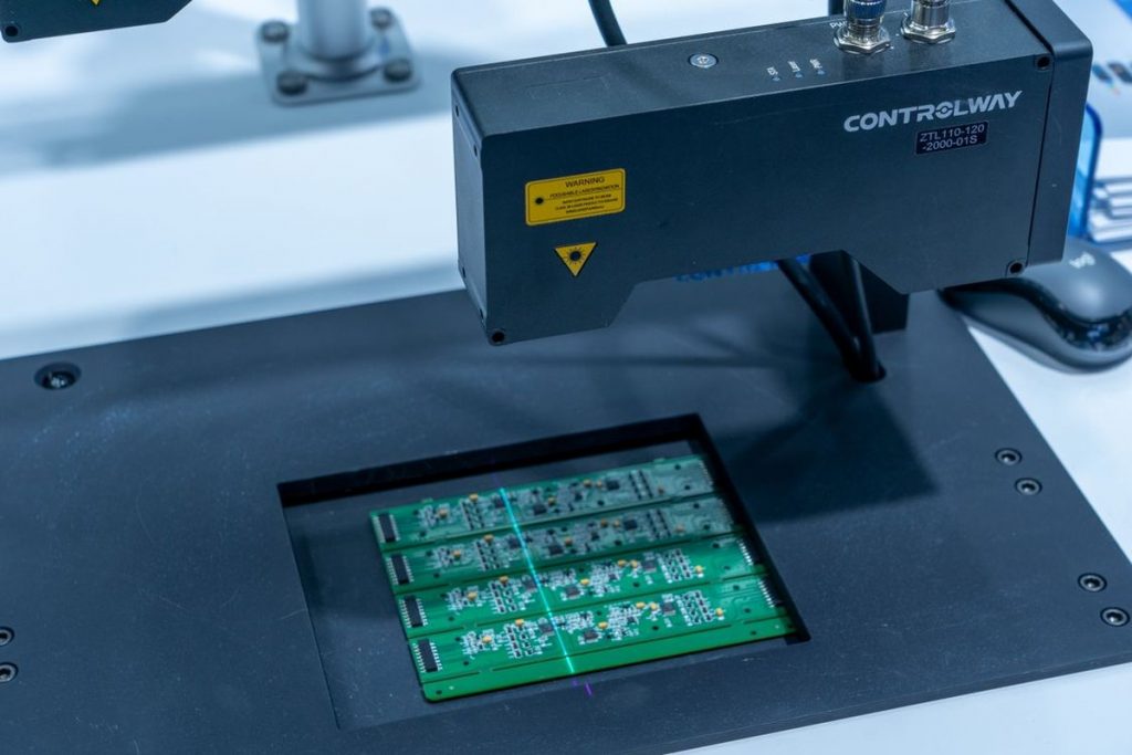
A machine vision system consists of five inseparable elements: the camera, the optics, the lighting, the trigger and the processing. Neglecting any one of these condemns the project, whatever the budget invested in software. This is the most misunderstood point: in machine vision, lighting is often more important than the camera.
Cameras: sensors, resolutions, shutters
Sensor choice conditions image quality. Industrial cameras use almost exclusively CMOS sensors, which have supplanted CCDs since the mid-2010s. For inspecting moving parts, a global shutter is essential: it exposes the whole sensor simultaneously, avoiding the rolling shutter distortion that corrupts measurements on moving objects. The market reference sensors — Sony IMX264 (5 megapixels), IMX250 (5 MP), IMX183, or On Semiconductor families — offer resolutions from 1 to 24 megapixels, more than enough for most applications.
A key point: in machine vision, resolution is not chosen “as large as possible” but “as large as necessary”. The empirical rule is that a defect must cover at least 3×3 pixels to be reliably detected. To measure a ±0.1 mm tolerance on a 100 mm part, the field of view must therefore provide a resolution of at least 0.03 mm per pixel — about 3,300 pixels across the relevant dimension: a 5 MP camera (2448×2048) is sufficient. Over-sizing the resolution increases cost, data volume and processing time without any reliability gain.
Optics: lenses and working distance
The lens determines the field of view (FOV) and working distance. Fixed focal length C-mount lenses (8, 12, 16, 25, 35 mm) cover the majority of cases. For very small parts (electronic components, connectors), telecentric lenses are the solution: they eliminate perspective, so measured dimensions remain identical regardless of part distance — essential for dimensional metrology. They cost more (often €1,000 to €3,000 versus €100 to €500 for standard optics) but save hours of calibration and debugging.
Lighting: the highest-return variable
Lighting is the most underestimated lever. Good lighting simplifies image processing to the point of making the algorithm trivial; bad lighting makes even the most sophisticated algorithm inoperative. Classic configurations:
- Backlight: the part is illuminated from behind, giving a high-contrast silhouette — ideal for dimensional measurement, burr detection, holes and cutouts.
- Coaxial lighting: light reflected at 90° through a semi-transparent mirror, perpendicular to the part — perfect for shiny, reflective surfaces (polished metal, packaging).
- Low-angle ring light: reveals reliefs and scratches through shadowing — typical for surface condition and scratch detection.
- Dark field: only scattering elements (scratches, asperities) appear bright on a dark background — extremely sensitive to micro surface defects.
LED sources dominate: long lifespan (50,000 h), spectral stability, and strobe synchronization capability. Wavelengths are chosen according to the material: red (660 nm) and infrared are classic for attenuating reflections on metal, UV for fluorescent markings, blue for contaminant detection. An optical bandpass filter paired with the lighting eliminates ambient light — a well-designed system works as well at night as under workshop neon lights.
Triggering and acquisition: GigE Vision, USB3 Vision, GenICam
The trigger synchronizes image capture with the part’s passage: photoelectric sensor, conveyor encoder, or PLC signal. At high throughput, the encoder is the reference: each pulse corresponds to a known conveyor displacement, and the image is taken at exactly the same position on the part every time.
For image transport, two standards dominate: GigE Vision (Gigabit Ethernet, with PoE to power the camera over the network cable) and USB3 Vision (up to 5 Gbit/s, lower latency, but cable limited to a few metres). Both rely on GenICam, the standard that unifies camera configuration APIs — any GenICam camera works with any GenICam software, regardless of manufacturer. This is what killed proprietary lock-in and drove prices down. For very high throughput or extreme frame rates, Camera Link and CoaXPress remain options, but they concern a minority of applications (electronics, very high speed web inspection).
From classical image processing to deep learning
Once the image is acquired, processing follows two broad families of approaches, often combined.
Classical processing: deterministic and controlled
Classical algorithms (led by OpenCV, free and open source) cover a huge range of checks: thresholding, contour analysis, mathematical morphology, circle and edge detection, template matching, distance measurement, OCR/barcode reading (Data Matrix, QR). They are deterministic: identical image, identical result, which simplifies validation and auditing. For 70 to 80% of industrial applications — presence/absence, dimensional measurement, positioning, code reading — classical processing is sufficient, and it is often the most robust and fastest choice to implement.
Deep learning: detecting non-reproducible defects
Deep learning changes the game for defects that no deterministic algorithm can describe: random scratches, porosity, shade variations, cosmetic defects. Three model families cover most needs:
- Classification: the image is classified “good” / “defective” — the simplest form, for global defect presence checks.
- Object detection (YOLO, Faster R-CNN): locates defects with bounding boxes and confidence levels — for counting and positioning defects.
- Semantic segmentation (U-Net): classifies every pixel — for precisely measuring a defect’s area, shape and orientation.
A particularly interesting approach for industry is anomaly detection, popularized by architectures such as PatchCore or PaDiM: the model is trained only on images of conforming parts, and flags any statistical deviation. The advantage is major: no need to collect images of defects (which are rare and often impossible to obtain in sufficient quantity) — only images of good parts, which are easy to produce. This is the approach of choice when defects are varied and unpredictable.
Models are trained on GPUs (a consumer-grade card is enough for datasets of a few hundred to a few thousand images) and exported to ONNX or TensorRT for inference. Embedded inference on NPUs or low-power GPUs (NVIDIA Jetson families, or Hailo and Intel Movidius accelerators) achieves processing times of 5 to 50 ms per image depending on complexity — perfectly compatible with standard production rates.
The right trade-off: hybrid systems
Industrial practice shows that the best systems are hybrid: classical processing handles deterministic checks (measurement, positioning, code reading), while deep learning only processes the appearance cases that classical imaging cannot qualify. This separation reduces the volume of data fed to the neural network (and therefore hardware cost) and keeps auditable checks where auditability is required.
Architecture: where does the intelligence live?
The architectural choice — centralized or edge processing — conditions cost, latency and system availability.
Edge computing: the image never leaves the workshop
For the vast majority of quality control applications, processing runs on an industrial PC (IPC) with a GPU or accelerator, located near the camera. The reasons are technical: latency must stay below the production rate (typically 100 to 500 ms per part), and the raw video stream from a 5 MP camera at 30 fps represents about 440 MB/s — pointless and expensive to transport. Edge processing also guarantees that inspection keeps working if the network goes down: a quality control system that depends on an Internet connection is an unacceptable risk.
The alternative of in-camera processing (smart cameras) exists: cameras integrating a processor and vision environment simplify deployment when the check is simple and localized. They are easier to install but less flexible for evolving the algorithm.
From inspection to data: the IoT uplink
This is where machine vision meets IoT. A modern quality control system is not content with a pass/fail verdict: it pushes results — part identifier, defect type, location, measurement — to a supervision platform. This uplink enables three high-value uses:
- Real-time quality statistics (defect rates per line, per shift, per batch) visible on dashboards, with alerts as soon as an indicator drifts.
- Correlation with process parameters: a drift in defect rate can be correlated with temperature, pressure, tool wear — the gateway to predictive maintenance.
- Full traceability: each part is associated with its inspection results, timestamped and archived — a decisive asset in customer claims and a prerequisite for certifications (ISO 9001, IATF 16949 in automotive).
Concretely, communication relies on standard industrial protocols: MQTT for the uplink to the platform, OPC UA for exchange with the PLC or MES, EtherNet/IP or Profinet when the system talks directly to the automation. Inspection results are timestamped and logged locally before sending, with a buffer guaranteeing no data is lost during a network outage.
Robotic integration: vision that guides the machine
Machine vision delivers its full value when coupled with robotics: the robot no longer follows a fixed program, it adapts to what it sees. This is vision-guided robotics (VGR).
Eye-in-hand and eye-to-hand: two geometries, two uses
Two camera configurations exist. In eye-in-hand, the camera is mounted on the robot arm near the end effector: it follows the motion, offering a close, changing view — ideal for picking parts from bins, checking specific points, or reading codes on parts with variable geometry. In eye-to-hand, the camera is fixed above or beside the scene: the view is stable, calibration is simpler, and it is the natural choice for inspecting parts at a fixed station or on a conveyor, and for guiding the robot to a known position.
In both cases, calibration is the critical step: it establishes the mathematical transformation (4×4 homogeneous matrix) between the camera frame and the robot frame. Quality calibration is verified by a reprojection error in the order of a tenth of a millimetre. Classic errors — non-planar calibration plate, too few poses, damaged target — translate into missed picks that are invisible at startup and costly in production.
Typical use cases
- Random pick & place: the camera detects the position and orientation of parts in bulk, the robot grasps them without pre-positioning — saving loading time and removing a presentation station.
- Inline conveyor inspection: each part is photographed on the fly, checked, and an ejection mechanism (air jet, arm, chute) removes non-conforming parts without stopping the line.
- Post-machining inspection: the robot presents the finished part in front of several cameras (multiple faces), measurements are compared to tolerances, and the decision is recorded with the part identifier.
- Machine loading/unloading: the robot locates raw parts (whose position varies), loads them into the machine tool, then unloads and inspects the machined part — a vision/robotics coupling that turns an isolated cell into an autonomous cell.
Robot ↔ vision communication
Communication between the vision system and the robot uses market standards: fieldbus protocols (EtherNet/IP, Profinet, EtherCAT) or OPC UA, with structured exchanges — position request, response with coordinates and orientation, acknowledgement. End-to-end latency (image capture → processing → transmission → robot motion) must be sized at design time: for pick & place, a typical budget is 100 to 300 ms between image trigger and motion command, which requires edge processing and low-jitter local communication.
Project methodology: how to avoid failure
A machine vision project rarely fails on technology — it fails on method. The proven sequence has four steps.
1. Precise functional specification
Everything starts with a quantified specification: which defects to look for, which tolerances to measure, at what rate, on which parts (and their variants), in which environment (vibration, dust, temperature, ambient light). The golden rule: a criterion that cannot be quantified cannot be validated. “Detect scratches” is insufficient; “detect scratches longer than 2 mm, visible to the naked eye, on the visible face, at 60 parts per minute” is a specification.
2. Feasibility study on real parts
Before any purchase, real images must be acquired with the intended camera and lighting, on real parts — including defective parts from production (or deliberately damaged parts). This step determines feasibility 80%. It must be done on site or with parts sent to the supplier, never with phone photos. Questions to settle: is contrast sufficient? Is lighting stable? Is the defect visible under these conditions?
3. Prototype (POC) in real conditions
The prototype installs the system on the line, in real production conditions, over a significant period (several weeks). Real false acceptance rates (missed defects) and false alarm rates (good parts rejected) are measured and compared to targets. Two indicators govern the decision: sensitivity (rate of detected defects) and specificity (rate of accepted good parts). A system that rejects 5% of good parts will be refused by operators, even if it detects 100% of defects.
4. Industrialization and change management
Production deployment integrates the system into the flow (conveyor, ejection chute, PLC interfaces), trains operators and maintenance staff, and defines the reject management procedure (manual confirmation inspection, root cause analysis). The human trap is real: a system perceived as a “judge” is sabotaged or bypassed; a system perceived as an assistant (displaying the part and the reason for rejection, helping the operator) is adopted. Displaying rejection images with the defect highlighted is not a gimmick: it is the main adoption factor.
ROI: what a vision system costs and returns
The cost of a complete machine vision system varies widely, but reliable order-of-magnitude figures exist:
- Simple inspection station (1 camera, lighting, classical processing, no robot): €10,000 to €25,000, hardware and integration included.
- Deep learning cell (GPU, image collection and labelling, training): €25,000 to €60,000.
- Vision + robot cell (pick & place or multi-face inspection): €50,000 to €120,000 depending on the robot and complexity.
On the other side, gains accumulate: elimination or reallocation of the manual inspection post (€35,000 to €45,000 per year fully loaded), reduction of rejects and returns (often 1 to 3% of revenue), 100% inspection instead of sampling, and — often the most profitable — the ability to justify higher throughput or win a new customer contract that required automated inspection. Field experience puts typical payback between 12 and 24 months. Beyond the direct calculation, automated inspection changes the commercial relationship: a supplier that can produce a complete inspection dossier for every batch (PPAP, conformity dossier) wins tenders that manual inspection never allowed it to bid for.
The mistakes that sink projects
A few recurring mistakes deserve listing, because they are expensive:
- Treating lighting as secondary: the first cause of failure. Choose the lighting first, then the camera.
- Testing with perfect parts: if the prototype has never seen a real defective part, production startup will reveal everything the system cannot do.
- Forgetting the environment: a dusty workshop, vibration, temperature variations change images. The system must be tested in the worst conditions, not the best.
- Confusing precision and repeatability: a 12 MP camera does not make a measurement more accurate if lighting varies or the part is not positioned reproducibly.
- Under-sizing software engineering: the operator interface, recipe management, result archiving, uplink to the information system often represent 50% of the effort — not 10%.
- Ignoring deep learning for cosmetic defects: persisting with thresholding rules for non-reproducible defects condemns the project; AI anomaly detection trains on conforming parts and solves the problem in weeks.
Conclusion: machine vision as a building block of the connected factory
Automated quality control with machine vision is no longer a large-group technology. Standardized GenICam cameras, open-source processing, accessible deep learning, IoT uplink of results: the technology stack is mature, costs have fallen, and returns on investment are measured in months. For an industrial SME, the sensible path is sequential: choose a high-stakes application (a currently manual inspection on a high-value part, or a recurring customer criterion), run a feasibility study on real parts, validate a prototype in production, then industrialize with quality data uplinked to supervision.
Machine vision is also, often, the first building block of a broader connected factory approach: once inspection results are digitized and centralized, correlation with production parameters opens the door to predictive maintenance, and full traceability strengthens the commercial position. This is exactly the kind of project where IoT and automation meet — and where a technical partner that masters embedded systems, industrial protocols and data uplink makes the difference between a laboratory demonstration and a system running 24/7 in production.
At IOTINNOV, we design and deploy this type of solution for industrial SMEs: from feasibility study to production system, including quality data uplink to supervision. If automated quality control is on your roadmap, a feasibility study on your real parts is the right first step — contact us.
À lire aussi
- AGV and AMR: Autonomous Navigation Architecture for Industry 4.0
- Collaborative Industrial Robot: 5 Concrete Uses
- Industrial cobotics for SMEs: integration guide — IoT supervision and predicti
Un besoin similaire sur votre parc ?
Échangeons 10 minutes — sans engagement
Parlons de votre besoin →